
Choosing Linear Regulated Power Supplies is not just a matter of matching the voltage printed on a device. A good choice depends on the load, current demand, noise sensitivity, and working environment. Linear designs can provide low ripple and steady output, which matters when powering sensitive analog circuits, audio equipment, or measurement systems. They are not automatically the best fit, though. Their pass components can generate noticeable heat, especially when input voltage is much higher than output voltage or the load draws substantial current.
Start with the basics: confirm the required output voltage and the load’s peak current, not only its typical draw. Check line and load regulation, ripple specifications, and available protections such as current limiting and thermal shutdown. Then consider the bench itself. A compact supply may fit neatly beside a prototype, but restricted airflow can raise its temperature during long tests. A fan can help, yet may add noise. Small details matter.
The specification sheet is useful, but it does not tell the whole story. Look for test conditions, output connectors, adjustment range, and credible measurements from the manufacturer. If the application is sensitive, verify performance with the actual load when practical; cables and changing current can affect what reaches the circuit. That sounds simple. It is not always. A sensible selection balances clean output, safe operation, heat, size, and cost rather than chasing one impressive number. This guide explains how to compare those factors and choose a supply that suits real working conditions.
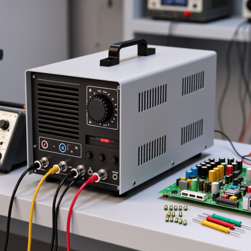
Set the output voltage to match the load’s specified operating range, not just its nominal value. A circuit rated for 12 volts may behave poorly if its supply drifts under changing demand. Check the regulator’s accuracy and line and load regulation figures. Then measure voltage at the load, where cable resistance can cause a small but important drop.
Choose a current rating with 20–30% headroom above the load’s highest expected draw. For a device that needs 1 amp, a supply rated around 1.2 to 1.3 amps offers room for startup surges and normal variation. Don’t size from average current alone; motors, lamps, and capacitive loads can briefly demand more. More capacity is not always better, though: verify the supply’s minimum load requirements and thermal limits.
Tips: Test the setup under realistic conditions. Use a meter to check output voltage while the load starts and runs. Linear supplies can dissipate substantial heat when input voltage is much higher than output voltage. Leave airflow around the unit, and recheck its temperature after sustained operation. Bench measurements can miss changes in a real enclosure.
How to Choose Linear Regulated Power Supplies
When choosing a linear regulated power supply, read line and load regulation together. They describe different output-voltage changes. Line regulation measures output movement when input voltage changes. Load regulation measures movement between light and heavy load conditions. Do not assume one value represents both behaviors.
Datasheets may show regulation as a percentage or in millivolts. Convert percentage into real voltage before judging performance. For a 5 V supply with 0.05% line regulation, the change equals 2.5 mV. A stated load regulation of 10 mV means the output may shift by 10 mV across the specified load range. Check the test conditions carefully. Input range, output current, temperature, and measurement points can change the result. Definitions also vary. One datasheet may use no-load to full-load voltage, while another uses a different reference. I once compared percentages without checking those conditions. That comparison looked precise, but it was not fair.
Tips: Use mV when the circuit has a strict voltage tolerance. Use percentages when comparing different output voltages. Calculate the actual error at your working voltage. Then add line and load effects conservatively. A 5 V sensor circuit may tolerate 20 mV, while a precision converter may not. Keep wiring resistance in mind, too. Datasheet numbers often exclude it. Real measurements can be slightly worse.
Compare line and load regulation using datasheet values in both millivolts and percent. Line regulation measures output change over the specified input-voltage range, while load regulation measures output change from minimum to maximum load.
Formula: Regulation (%) = Regulation (mV) ÷ Nominal Output Voltage (mV) × 100. Lower values indicate better output-voltage stability.
How to Choose Linear Regulated Power Supplies
Ripple and noise deserve more attention than a single headline number. A linear supply rated at 2 mV RMS may show 10 to 20 mV peak-to-peak noise. The waveform shape changes that relationship. A clean sine wave differs greatly from sharp switching spikes.
Check the specification bandwidth carefully. The 20 Hz–20 MHz window is common industry practice. IEC 61204-3:2019 provides measurement guidance for low-voltage power supplies and stresses defined test conditions. Without a stated bandwidth, “low noise” means little. A 100 kHz measurement can hide fast edges above that limit. Use a short spring ground connection, not a long oscilloscope lead. Long wires can act like antennas. They may create impressive, but false, peaks.
Test at the real load current. Record input voltage, temperature, warm-up time, and output setting. Compare RMS noise and peak-to-peak noise separately. IEEE Std 1057-2017 also emphasizes bandwidth, sampling, and instrument uncertainty in waveform measurements. That matters when the result is only a few millivolts. I have seen specifications look excellent until the load changed suddenly. The supply was stable, but the test was too gentle. A quieter reading is not always a better supply. Check the actual circuit, especially sensitive converters, sensors, and precision amplifiers. Candor helps here: published figures rarely predict every bench condition.
| Specification or Check | What to Look For | Useful Data or Example | Why It Matters |
|---|---|---|---|
| Ripple-and-noise bandwidth | Compare measurements made over the same stated frequency range. | 20 Hz–20 MHz is a commonly used specification bandwidth. | A different bandwidth can produce a different RMS result, so figures measured over unlike ranges are not directly comparable. |
| RMS units | Check whether the value is stated in mV RMS or µV RMS. | 1 mV RMS = 1,000 µV RMS; 0.25 mV RMS = 250 µV RMS. | Consistent units make it easier to compare supply specifications without mistaking a unit conversion for a performance difference. |
| RMS versus peak-to-peak | Do not treat RMS and peak-to-peak values as interchangeable. | For a pure sine wave only, Vpp = 2√2 × VRMS (about 2.83 × VRMS). | Real ripple and noise may contain multiple frequencies and irregular waveforms, so there is no single general conversion from RMS to peak-to-peak. |
| Measurement conditions | Check the stated input voltage, output load, temperature, and measurement setup. | Compare figures only when these conditions are equivalent or clearly documented. | Ripple and noise can vary with operating conditions; an isolated number may not represent performance in the intended application. |
| Load points | Look for readings at more than one output load, including the intended operating load. | A useful evaluation can include light load, typical load, and rated load. | Output noise and regulation may change as the supply’s load changes. These are evaluation points, not universal mandatory test points. |
| Input-voltage points | Check whether ripple-and-noise performance is specified across the intended input range. | Compare low, nominal, and high input conditions when those values are provided. | Matching the test conditions to the real input range helps reveal whether performance is consistent in the application. |
| Ripple versus broadband noise | Check whether the specification combines periodic ripple and broadband noise or reports them separately. | Both may contribute to a single RMS ripple-and-noise figure. | Separate measurements, when available, can help identify whether mains-related components or higher-frequency noise are the main concern. |
| Measurement method | Check the stated probe, grounding, and instrument bandwidth limitations. | Use a short probe ground connection and the same measurement bandwidth when making comparisons. | Measurement setup can pick up unwanted interference or change the observed high-frequency content. |
| Example specification reading | Interpret the value together with its bandwidth and test conditions. | Example only: 0.8 mV RMS over 20 Hz–20 MHz at a stated input voltage and load. | This illustrates how a specification may be presented; it is not a measured value for a particular power supply or a universal performance target. |
| Application requirement | Set an acceptable ripple-and-noise limit based on the load circuit’s sensitivity. | There is no single ripple-and-noise limit that is suitable for every application. | Precision analog, sensor, and low-noise circuits may require different supply performance from less noise-sensitive loads. |
A linear supply may look quiet on an oscilloscope, yet its rectifier can carry 100 or 120 Hz ripple. The frequency depends on the local mains frequency and full-wave rectification. Ripple rises when load current increases or the reservoir capacitor ages. A useful estimate is Vripple ≈ Iload ÷ (2fC). For example, a 0.5 A load and a small capacitor can create several volts of ripple before regulation. Check the waveform under real load, not only at idle.
Tips:
Measure ripple across the reservoir capacitor with a short ground connection. Confirm the regulator has enough headroom at the ripple trough. Also check the capacitor’s ripple-current rating and temperature rating. A larger capacitor helps, but it can increase startup current and stress the rectifier.
Heat loss is often the harder limit. A linear regulator dissipates approximately (Vin − Vout) × Iload. Dropping 12 V to 5 V at 0.5 A produces about 3.5 W of heat. That may require a substantial heatsink, airflow, or lower input voltage. Keep the enclosure temperature in mind. It is easy to underestimate.
In practice, I would test the supply for several hours at the highest expected ambient temperature. One design mistake is choosing a regulator from its nominal output alone; ripple valleys, mains variation, and component tolerance can change the result. Select voltage, current, thermal margin, and measured ripple together.
When choosing a linear regulated power supply, treat isolation as a measured safety feature, not a marketing phrase. The U.S. Bureau of Labor Statistics recorded 145 fatal work injuries involving electrical exposure in its 2022 Census of Fatal Occupational Injuries. That figure is not specific to bench supplies, but it highlights the cost of overlooking electrical hazards. Small details matter.
Check the exact model’s safety certificate and test report for IEC 61010-1 compliance. Confirm the input-to-output isolation voltage, working voltage, insulation classification, creepage and clearance distances, and permitted pollution degree. A brief dielectric withstand test, such as a 3 kV hipot test, does not by itself establish a safe continuous working voltage. Read the conditions attached to the rating.
Match the supply’s overvoltage category and altitude limits to the installation. A unit used on a laboratory bench may face different transient conditions from equipment connected directly to a building’s mains supply. Check whether protective earth is required, and inspect the enclosure and output terminals for accessible conductive parts. If the datasheet gives only a test voltage, ask for the rated working voltage and applicable certification details. I would not rely on a reassuring label alone; documentation can still leave important questions unanswered.
Match the load’s specified operating range, not only its nominal voltage. A “12 V” circuit may misbehave when demand changes. Measure voltage at the load, because cable resistance can reduce it.
Choose a rating 20–30% above the highest expected draw. A 1 amp load usually needs about 1.2–1.3 amps. Startup surges matter. Average current alone can mislead.
No. Check minimum-load requirements and thermal limits first. Some supplies behave poorly with very light loads. More capacity is not automatically safer.
Measure output voltage while the load starts and runs. Test realistic conditions, not only an empty bench. Check temperature after sustained operation. Airflow matters.
Line regulation describes output changes when input voltage changes. Load regulation describes changes between light and heavy loads. They measure different behaviors.
Convert percentages into actual voltage changes. For 5 V at 0.05% regulation, the change is 2.5 mV. Use millivolts for strict tolerances. Check test conditions carefully.
Test conditions may exclude cable resistance and enclosure temperature. Definitions can differ between documents. I once compared percentages without checking conditions. That comparison was not fair.
Check the exact model’s certification and test report for IEC 61010-1 compliance. Verify isolation, working voltage, insulation class, creepage, and clearance. Also check pollution degree, overvoltage category, and altitude limits.
No. A brief 3 kV test does not prove continuous working-voltage safety. Confirm protective-earth requirements and accessible conductive parts. Do not trust a reassuring label alone.
Choosing Linear Regulated Power Supplies requires more than selecting a nominal voltage. First, set the required output voltage and current, then include a 20–30% current margin to accommodate startup surges, load variation, and future changes. When comparing models, review both line regulation and load regulation using the values provided in the datasheet, expressed as percentages or millivolts. Lower figures generally indicate more stable output under changing input or load conditions.
Ripple and noise should also be evaluated in mV RMS, while checking the measurement bandwidth, which is often specified from 20 Hz to 20 MHz. Designers must account for 100/120-Hz rectifier ripple and the heat generated by voltage drop in a linear circuit, especially at higher currents. Finally, verify the unit’s isolation, insulation, and applicable IEC 61010-1 safety ratings to ensure the supply is suitable for the intended equipment and operating environment.