
Engineered for extreme electromagnetic interference (EMI) rejection, zero-thermal drift, and fast response times across industrial and grid environments.
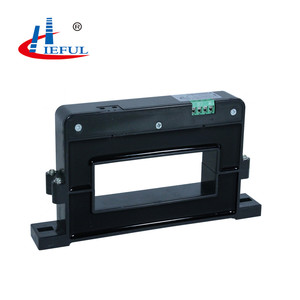
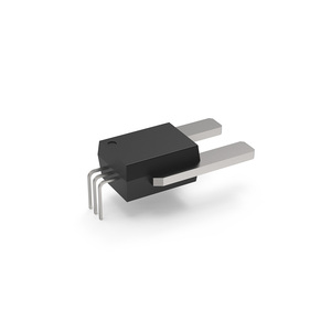
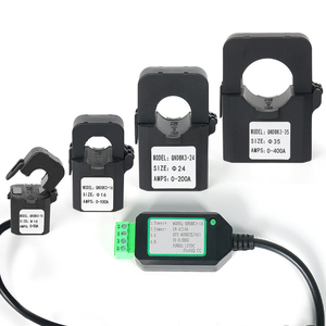
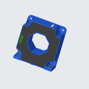
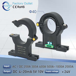
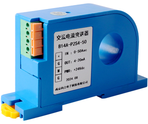
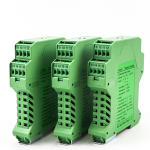

Current transducers act as the primary sensory organ in modern power conversion architectures, variable frequency drives (VFDs), solar central inverters, and battery energy storage systems (BESS). Obtaining sub-percent accuracy across varying ambient temperatures and high electromagnetic noise environments demands rigorous magnetic core design, ASIC integration, and zero-drift amplification stage topologies.
Our OEM and ODM engineering facilities specialize in solving critical signal distortion problems caused by parasitic capacitance, high transient dV/dt switching from Silicon Carbide (SiC) and Gallium Nitride (GaN) power stages, and DC saturation of magnetic cores.
Selecting the correct transducer topology requires balancing measurement bandwidth, DC coupling capabilities, thermal offset drift, and insertion loss:
A parametric evaluation framework to assist hardware system architects in specifying optimal sensor modules for OEM equipment integration.
| Transducer Architecture | Primary Current Range | Overall Accuracy Class | Bandwidth (-3dB) | Response Time | Thermal Drift (-40 to 85°C) | Target Applications |
|---|---|---|---|---|---|---|
| Open-Loop Hall Effect | 5A – 1500A | ±1.0% to ±1.5% | DC to 50 kHz | < 3.0 to 5.0 µs | ±0.05% / °C | UPS systems, motor overload control, battery monitoring |
| Closed-Loop Hall Effect | 10A – 5000A+ | ±0.2% to ±0.5% | DC to 200 kHz | < 0.5 to 1.0 µs | ±0.01% / °C | VFD inverters, traction drives, EV fast chargers |
| Fluxgate Precision Transducer | 50A – 3000A | ±0.005% to ±0.05% | DC to 500 kHz | < 0.2 µs | < 1 ppm / K | Precision lab power supplies, MRI, power analyzers |
| Split-Core Modbus Digital CT | 10A – 2000A | ±0.5% to ±1.0% | 50 Hz / 60 Hz AC | 100 ms (RS485 cyclic) | ±0.03% / °C | Industrial IoT, energy auditing, smart grid SCADA |
| Rogowski Coil Transducer | 100A – 50kA+ | ±0.5% to ±1.0% | 1 Hz to 1 MHz | < 0.1 µs | Near Zero Core Saturation | Pulsed power, arc furnace monitoring, high-current AC |
How next-generation semiconductor topologies, renewable energy expansion, and smart grid automation are reshaping current measurement demands.
As power electronics migrate from traditional IGBTs to Silicon Carbide (SiC) and Gallium Nitride (GaN) switching devices, operating frequencies are pushing past 100 kHz with dV/dt slew rates exceeding 50 kV/µs. Modern OEM current transducers are incorporating internal electrostatic Faraday shielding between primary conductors and secondary sensing ASIC elements to suppress common-mode capacitive noise coupling.
Traditional analog output signals (4-20mA or 0-10V) are increasingly yielding to intelligent digital transducers equipped with embedded microcontrollers. Integrated RS485 Modbus RTU, CANopen, and Ethernet/IP protocols eliminate external analog-to-digital converter (ADC) noise degradation, allowing direct fieldbus connectivity for Industry 4.0 predictive maintenance and energy telemetry.
Thermal zero offset drift remains a principal cause of measurement error in high-temperature environments like solar central inverters and automotive traction drives. Advanced OEM current sensors utilize active chopper-stabilized amplifier topologies that continuously auto-zero operational amplifier offset voltages, achieving sub-millivolt drift over a -40°C to +125°C thermal envelope.
Analyzing key commercial, regulatory, and supply chain shifts impacting enterprise buyers of current and voltage measurement transducers.
Global original equipment manufacturers (OEMs) are systematically reducing single-source dependencies by specifying current transducers with standardized mechanical footprints and pin-to-pin functional equivalence to legacy components (such as ACS770, LEM HAS/LA series replacements). Our OEM engineering division supports drop-in replacement prototyping to accelerate dual-sourcing qualification.
For smart factory upgrades, grid sub-station modernizations, and energy management installations, system integrators prioritize split-core transducers. Split-core designs eliminate the need to disconnect primary power cables or busbars, reducing commissioning downtime and labor costs by up to 70% during field retrofit operations.
Enterprise procurement teams are placing higher emphasis on TCO metrics—evaluating low insertion resistance (which minimizes parasitic heat dissipation inside enclosed cabinets), Mean Time Between Failures (MTBF > 1,500,000 hours), and long-term calibration stability over initial piece-part acquisition pricing.
From custom busbar aperture geometry to application-specific ASIC programming, our engineering organization provides turnkey design-to-production capability for global enterprise partners.
Comprehensive answers regarding current transducer selection, technical parameter verification, custom lead times, and global shipping standards.
Open-Loop Hall Effect transducers measure magnetic flux generated by primary current using a Hall element integrated within a magnetic core gap. The amplified Hall voltage forms the direct output. Closed-Loop (Zero-Flux) transducers continuously generate a compensating current through a secondary winding to nullify primary magnetic flux inside the core. Closed-loop units offer substantially higher linearity (typically <0.1% vs >1.0%), faster response times (<1µs vs 3-5µs), and lower thermal drift, making them preferred for precision power conversion.
Yes. Our engineering division specializes in OEM/ODM design modifications. We can engineer custom aperture openings (round, rectangular, multi-slot), custom mounting ears, specific wire harness termination connectors (Molex, TE Connectivity, JST), or compact split-core housings tailored to fit within pre-existing electrical cabinet constraints.
High switching speed devices generate fast voltage transients ($dV/dt$) that can capacitively inject noise into internal sensor circuitry. Our high-frequency closed-loop transducers feature integrated electrostatic Faraday shielding between the primary busbar area and the secondary internal sensing elements, effectively routing common-mode capacitive currents back to ground without corrupting output signal integrity.
Standard analog outputs include 0-5V DC, 0-10V DC, 4-20mA current loops (two-wire or three-wire configurations), and instantaneous proportional AC/DC voltage outputs ($\pm$4V, $\pm$5V, or $\pm$10V at nominal current). Digital models support isolated RS485 Modbus RTU interface with configurable baud rates (default 9600 bps), parity bits, and device slave addressing.
Our transducer lines are designed in accordance with international safety standards including IEC 61800-5-1, IEC 61010-1, and UL 94-V0 enclosure flammability ratings. Standard galvanic isolation withstand voltages range from 2.5 kV AC for 1 minute up to 6.0 kV RMS high-voltage impulse ratings for demanding medium-voltage distribution equipment.
For standard catalog configurations, sample quantities are available with no minimum order quantity (MOQ) restriction. Engineering samples for standard or minor modification units typically ship within 3 to 5 business days. Full custom ODM projects (requiring new magnetic core tools or custom plastic molds) average 2 to 4 weeks for initial prototype delivery.
Thermal offset drift is mitigated through precision laser trimming of thick-film resistor networks on internal substrates, implementation of zero-drift operational amplifier ICs with internal chopper stabilization, and rigorous temperature-compensated current sources driving the internal Hall sensor bridge circuits.
Yes. All current transducers manufactured at our facilities comply with EU Directive 2011/65/EU (RoHS 2.0) and REACH (EC 1907/2006) regulations regarding restricted hazardous substances. Full material declaration certificates are supplied alongside project documentation files upon contract confirmation.
Accelerate your hardware engineering timeline with validated precision current transducers, customized core geometries, and guaranteed export quality assurance.