
Engineered for high efficiency, wide input voltage ranges, and ultra-compact power density across AC-DC and DC-DC topologies.

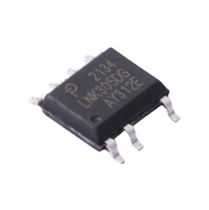

Combining rugged military-grade reliability, strict ISO 9001:2015 quality frameworks, and deep magnetic coupling expertise.
Every flyback transformer, custom inductor, and integrated switching IC power supply is designed, manufactured, and serialized under rigorous quality management systems. Full traceability supports defense, aerospace, and medical program audits.
Utilizing premium grade MnZn and NiZn soft ferrite cores alongside optimized Litz wire coil configurations, our flyback converters minimize switching losses, suppress EMI at high operating frequencies (up to 500kHz), and maintain thermal equilibrium.
Off-the-shelf topologies rarely solve complex isolation challenges. We engineer custom vertical and horizontal bobbin flyback transformers (EE13, EE16, EE25, EFD20) tuned to precise primary-to-secondary turns ratios and multi-output auxiliary rails.
An in-depth analysis of energy storage magnetics, active clamping, and semiconductor integration for switching power supplies.
Unlike conventional forward converters where energy is transferred instantaneously from primary to secondary windings during the switch ON-state, the flyback converter operates strictly as a coupled inductor system. During the ON-time ($t_{ON}$) of the primary switching transistor (MOSFET or GaN FET), current ramps up linearly through the primary winding, storing energy in the air gap of the magnetic core according to the equation:
When the primary switch turns OFF ($t_{OFF}$), the polarity of the windings reverses due to Faraday's law of induction (Lenz's Law). The secondary diode becomes forward-biased, allowing the magnetic energy stored in the core gap to collapse and transfer to the output filter capacitor and connected load. This fundamental separation of energy storage and energy transfer makes the flyback topology uniquely advantageous for isolated step-up, step-down, and multiple-output power conversion stages below 150 Watts.
A primary design challenge in high-frequency flyback converters is managing leakage inductance ($L_{lk}$)—the portion of primary magnetic flux that fails to couple with the secondary winding. When the primary MOSFET opens abruptly, the energy stored in $L_{lk}$ cannot instantly discharge to the secondary. Left unmitigated, this produces severe voltage spikes ($\Delta V = L_{lk} \cdot \frac{di}{dt}$) across the MOSFET drain-source junction, risking catastrophic semiconductor breakdown.
Traditional designs utilize a passive RCD (Resistor-Capacitor-Diode) Snubber Network to dissipate this spike energy as heat. However, modern high-density power systems increasingly adopt Active Clamp Flyback (ACF) architectures. By replacing the passive snubber diode with an auxiliary low-side or high-side switch paired with a clamp capacitor, the leakage inductance energy is recycled back to the input, enabling Zero Voltage Switching (ZVS) across the primary switch. ZVS eliminates capacitive turn-on losses, allowing switching frequencies to scale from 65kHz up to 500kHz while dramatically reducing core size.
Selecting the optimal operating mode dictates transformer core sizing, thermal behavior, and control loop stability:
| Design Parameter | Continuous Conduction Mode (CCM) | Discontinuous Conduction Mode (DCM) | Quasi-Resonant (QR) / ZVS Mode |
|---|---|---|---|
| Secondary Current Waveform | Does not decay to zero before next ON cycle | Decays to zero prior to end of switching period | Decays to zero; turns ON at valley voltage |
| Peak Primary Current ($I_{peak}$) | Lower (reduced I2R conduction losses) | Higher (requires larger MOSFET peak current rating) | Medium (variable frequency tracking) |
| Transformer Core Size | Larger core required (prevents flux saturation) | Smaller core volume | Optimized compact core geometry |
| Control Loop Dynamics | Complex (Right-Half-Plane Zero present) | Simple 1st-order system transfer function | Variable frequency PWM; simplified compensation |
| EMI Signature | Hard switching produces higher high-frequency EMI | Moderate EMI; lower reverse recovery diode stress | Lowest EMI due to soft-switching ZVS |
Key technological shifts global buyers must evaluate when sourcing flyback transformers and switching controller ICs.
Silicon MOSFETs are approaching their physical limits in switching speed and power density. Supply chain procurement data shows a massive shift toward Gallium Nitride (GaN) power stages embedded directly within off-line flyback ICs. GaN allows power supply designers to operate flyback converters above 200kHz to 1MHz without suffering severe thermal derating. This shrinks transformer magnetic volumes by up to 50%, driving high-density USB-PD fast chargers, industrial auxiliary power units, and server standby modules.
Automated high-mix procurement favors consistency. Traditional wire-wound bobbin transformers suffer from manual manufacturing variances in leakage inductance and parasitic capacitance. Modern industrial buyers are mandating Planar Flyback Transformers utilizing multi-layer PCB windings and low-profile E-cores. Planar structures guarantee 100% repeatable parasitic parameters, exceptional creepage distance compliance, and low profile heights under 10mm for space-constrained electronics.
Industrial IoT automation, renewable energy storage systems (BESS), and electric vehicle (EV) powertrains demand auxiliary flyback DC-DC converters capable of operating across immense input spans—such as 14VDC to 160VDC for railway applications or 200VDC to 1200VDC for high-voltage solar inverters. Sourcing strategies now prioritize flyback controllers with wide input withstand ratings to consolidate SKU varieties.
Global regulatory mandates—including DoE Level VI (USA), CoC Tier 2 (EU), and IEC 62368-1 safety standards—require off-line flyback power supplies to consume less than 75mW (or even 30mW) during no-load standby conditions. Procurement teams are specifying integrated switcher ICs (such as Power Integrations TinySwitch or ON Semi NCP series) featuring burst-mode operation and jittered switching frequencies to pass CISPR32 / EN55032 Class B EMI specs effortlessly.
How next-generation component topology is reshaping switching power supply performance.
Optocoupler-less feedback mechanisms are rapidly replacing legacy optocouplers. By sensing primary-side auxiliary winding waveforms (Primary-Side Regulation / PSR) or utilizing digital capacitive feedback isolators, engineers eliminate optocoupler aging degradation and gain tighter ±1% voltage regulation across extreme temperature ranges (-40°C to +125°C).
Replacing secondary Schottky diodes with active Synchronous Rectifier MOSFETs dramatically reduces forward conduction voltage drops ($V_F$). Integrated SR flyback controller ICs precisely monitor secondary winding voltage to trigger low-RDS(on) FETs, raising total power supply system efficiency from ~82% to over 92%.
As flyback converters penetrate medical (IEC 60601-1 2xMOPP) and high-voltage EV traction inverters, transformer insulation technology has evolved. Using triple-insulated wire (TIW), margin tape, and specialized encapsulation resins, manufacturers deliver compact flyback transformers withstanding 4000VAC to 5000VAC isolation tests.
Expert answers to critical technical and purchasing inquiries regarding flyback converters and custom transformers.
Need custom turn ratios, specialized core geometries, or urgent volume production? Speak directly with our senior application engineering team today for instant technical guidance and competitive factory-direct pricing.