Engineering Insights & Architecture
What Is an N+1 Redundant Power System and How Does It Ensure Zero Downtime?
An in-depth technical analysis for power system architects, electrical engineers, and global procurement managers specified in continuous-duty applications.
In modern industrial automation, aerospace ground control, high-density AI data centers, medical devices, and defense installations, a single power supply failure can trigger catastrophic downtime, lost telemetry, data corruption, or multi-million-dollar operational halts. N+1 Redundant Power Systems are specifically designed to eliminate single points of failure by deploying parallel power modules backed by active or passive isolation circuits.
The Mathematics of N+1 Redundancy: Operational Logic
The term "N+1" defines a fault-tolerant configuration where N represents the exact number of power supply units required to deliver 100% of the maximum system load, and +1 indicates an extra independent power unit operating in parallel. Under normal operating conditions, all modules share the load proportionally or operate in continuous active standby. If any single power module suffers an AC line disruption, internal short circuit, open loop, thermal runaway, or component aging failure, the remaining active units instantaneously absorb the complete electrical load without voltage drop, transient spikes, or microsecond interruptions to downstream electronics.
Statistical Reliability Comparison: Single vs. Redundant Power
If a standalone power supply exhibits a Mean Time Between Failures (MTBF) of 100,000 hours, its failure probability over a given timeframe is measurable. However, in an Acopian N+1 Redundant System with integrated ORing isolation diodes and independent AC/DC inputs, system MTBF increases exponentially—often exceeding 1,500,000+ hours. This moves system reliability from standard commercial availability (99.9%) to true defense/mission-critical grade "Six Nines" (99.9999%).
Core Components of a True Fault-Tolerant Redundant System
Simply connecting two standard power supplies in parallel is not a redundant system. A true N+1 redundant power architecture requires precise engineering controls:
- Internal Isolation Diodes (ORing Circuitry): Prevents a shorted output stage in one failed power supply from pulling down the entire DC voltage bus. Acopian systems feature rugged low-loss schottky diodes or active MOSFET isolation.
- Active Forced Current Sharing: Ensures equal thermal distribution across all connected modules. By equalizing output stress, component lifetimes increase by up to 300%.
- Built-in Status Telemetry & Relays: Form-C relay contact closures, LED indicators, and TTL status lines notify plant management or automated supervisory systems immediately upon a module failure.
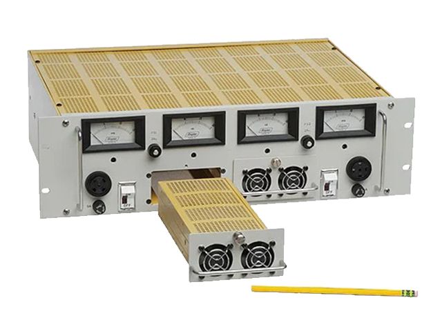
- Hot-Swappable Chassis Design: Enables technicians to replace a damaged power supply module live without disconnecting input AC power or turning off the load.
- Dual Independent Input AC Feeds: Allows primary power input from utility grid A and backup power input from UPS or generator grid B.