Engineering Insight & Technical Analysis Deconstructing Modern Telecom Power Systems: Electrical Isolation, Thermal Derating, and N+1 Redundancy
When telecommunication systems engineers evaluate potential vendors for Telecom Power Systems, the criteria extend far beyond simple voltage and current ratings. Modern carrier-grade installations—spanning Central Offices (CO), Remote Radio Heads (RRH), Baseband Units (BBU), Earth Satellite Stations, and Subsea Landing Terminals—demand continuous power delivery under severe electrical stress, line transients, and environmental extremes.
Below is an in-depth engineering breakdown addressing critical design parameters, semantic search queries, and operational requirements that technical buyers evaluate during system qualification.
1. Why -48V DC Remains the Benchmark for Global Telecommunications
A frequent query among telecommunications infrastructure planners is why the industry continues to standardize on negative 48 Volts (-48V DC) rather than positive voltages or standard 120/240 V AC distribution. The historical and electro-chemical rationale is grounded in three key engineering principles:
- Galvanic Corrosion Suppression: In moist outdoor cabinets and underground vaults, positive DC voltages accelerate metallic electrolytic corrosion on wet copper cables and grounding chassis. Applying a negative potential (-48V DC with positive ground) causes copper to act as a cathode rather than an anode, drastically reducing galvanic destruction over decades of operational life.
- Human Safety Thresholds: Telecommunication standard ETSI EN 300 132-2 defines SELV (Safety Extra-Low Voltage) limits around 60V DC. Operating at nominal -48V DC (with float voltages reaching up to 56V-58V DC) stays safely beneath lethal electrical shock thresholds, allowing field technicians to wire backplanes and service battery banks without bulky high-voltage PPE.
- Uninterruptible Battery Floating: -48V DC telecom rectifiers connect directly in parallel across valve-regulated lead-acid (VRLA) or Lithium Iron Phosphate (LiFePO4) battery strings. When AC utility grid power fails, the battery bank instantly discharges into the load with zero transfer delay and zero millisecond switching transient.
2. High Efficiency & Thermal Management in Outdoor Edge Cabinets
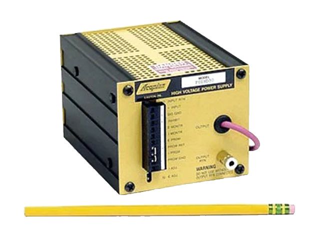
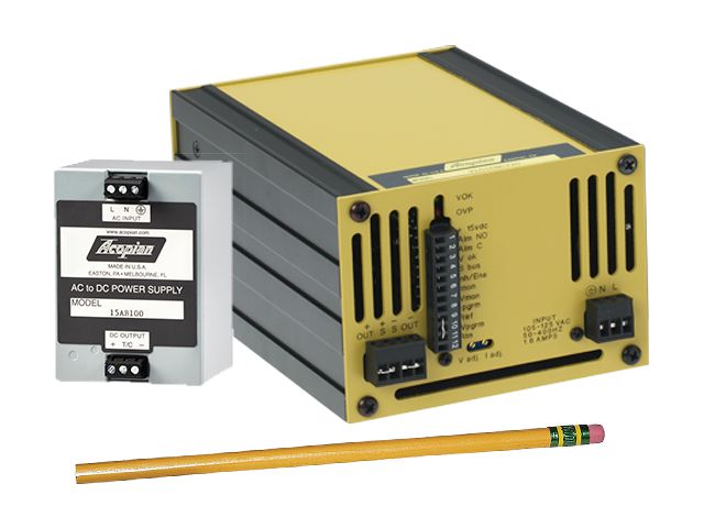
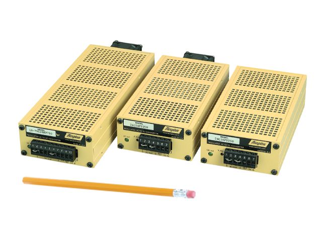
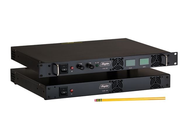
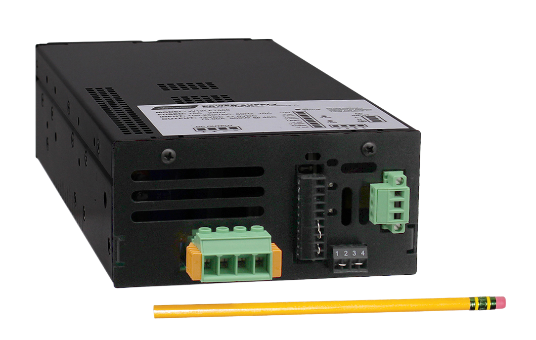
As 5G macro sites and small cells transition to dense outdoor enclosures, heat buildup becomes the primary cause of power module MTBF degradation. Acopian Telecom Power Systems employ high-density switching topologies utilizing advanced Silicon Carbide (SiC) and Gallium Nitride (GaN) power semiconductors to achieve electrical conversion efficiencies exceeding 96%.
By minimizing internal heat dissipation (I²R loss), Acopian rectifiers decrease internal junction temperatures and eliminate the need for high-maintenance external liquid cooling. Conduction-cooled and natural convection-cooled options allow sealed NEMA 4X enclosures to operate reliably without drawing contaminated outside air into sensitive component chambers.
Acopian Technical Baseline: Telecom Thermal Operating Envelope
All Acopian standard telecom power supplies undergo 100% full-load burn-in testing. Rated for continuous full-output operation from -20°C to +71°C ambient temperatures. Derating curves are linear and fully documented in every downloadable datasheet, eliminating guesswork during thermal cabinet modeling.
3. Low Ripple & EMI Immunity for High-Frequency Wireless Signals
In high-speed data transmission networks and multi-band RF amplifiers, voltage ripple on the DC rail translates directly into phase noise, jitter, and elevated Bit Error Rates (BER). Switching noise spikes can distort signal constellations in 64-QAM and 256-QAM wireless microwave backhauls.
Acopian telecom power rectifiers and linear regulated units integrate multi-stage LC filter networks and active Power Factor Correction (PFC > 0.99). Conducted emissions comply strictly with FCC Part 15 Class B and CISPR 32 standards, protecting nearby radio cards and optical transceivers from electromagnetic interference.